Gigabit Ethernet Cable Pinout, EIA/TIA 568A and EIA/TIA 568B standard
Gigabit Ethernet (1 Gbps) and 10 Gigabit Ethernet (10 Gbps) standards have a different pinout when compared with Ethernet (10 Mbps) and FastEthernet (100 Mbps) standards.
In previous lesson, we had discussed about Ethernet (10 Mbps) and FastEthernet (100 Mbps) Straight-through and Cross-over cables. In Ethernet (10 Mbps) and FastEthernet (100 Mbps) standards only two pairs (four wires) of wires in twisted pair cables are used. In earlier Ethernet stabEthernet (10 Mbps) and FastEthernet (100 Mbps) standards, one pair of wire in twisted pair cable are used for transmitting data and the other pair is used for receiving data.
Following table lists the pins used for data transfer in Ethernet (10 Mbps) and FastEthernet (100 Mbps) standards
| Pin Number | Color | Function |
|---|---|---|
| 1 | White Green | TX+ |
| 2 | Green | TX- |
| 3 | White Orange | RX+ |
| 4 | Blue | Not Used |
| 5 | White Blue | Not Used |
| 6 | Orange | RX- |
| 7 | White Brown | Not Used |
| 8 | Brown | Not Used |
Please refer below image to understand which pins are used for transmitting data and receiving data between a Computer and a Switch in Ethernet (10 Mbps) and FastEthernet (100 Mbps) standards.

Above described way of data transmission in Ethernet (10 Mbps) and FastEthernet (100 Mbps) standards is not applicable for Gigabit Ethernet (1 Gbps) and 10 Gigabit Ethernet (10 Gbps) standards. In Gigabit Ethernet (1 Gbps) and 10 Gigabit Ethernet (10 Gbps) standards, all four pairs (all eight wires) of twisted pair cables are used for transmitting data and receiving data.
The main difference between earlier Ethernet standards (10 Mbps Ethernet and 100 Mbps FastEthernet) and latest Ethernet standards (1 Gbps Gigabit Ethernet and 10 Gbps Gigabit Ethernet) are listed below.
• All the eight wires (four pairs) are used for data transmission.
• Wires can transmit and receive data simultaneously (bi-directional).
Note that "BI" stands for bi-directional. DA, DB, DC and DD stands for "Data A", "Data B", "Data C" and "Data D", respectively.
In Gigabit Ethernet and 10 Gigabit Ethernet data transmission, the transmit and receive signals are superimposed on top of each other. Thus, if the sender knows what he sent, he can extract what he has received from other end.
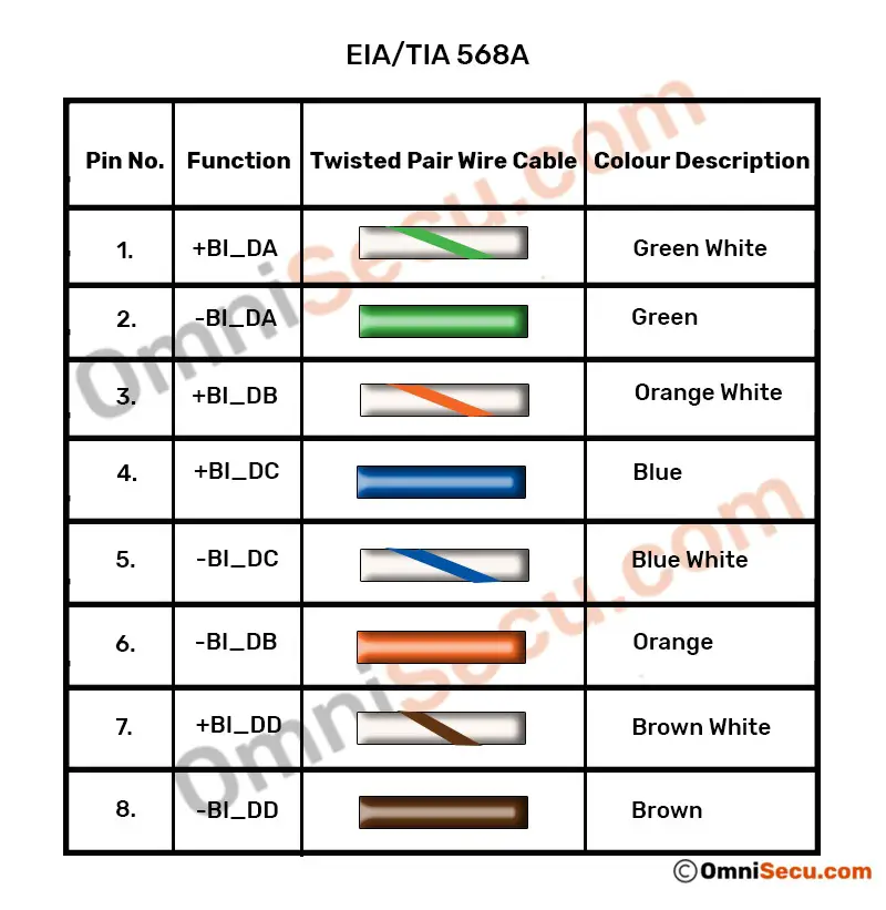
Please refer following table to learn Gigabit Ethernet cabling pinout, according to EIA/TIA 568A standard.
| Pin Number | Color | Function |
|---|---|---|
| 1 | Green White | +BI_DA |
| 2 | Green | -BI_DA |
| 3 | Orange White | +BI_DB |
| 4 | Blue | +BI_DC |
| 5 | Blue White | -BI_DC |
| 6 | Orange | -BI_DB |
| 7 | Brown White | +BI_DD |
| 8 | Brown | -BI_DD |
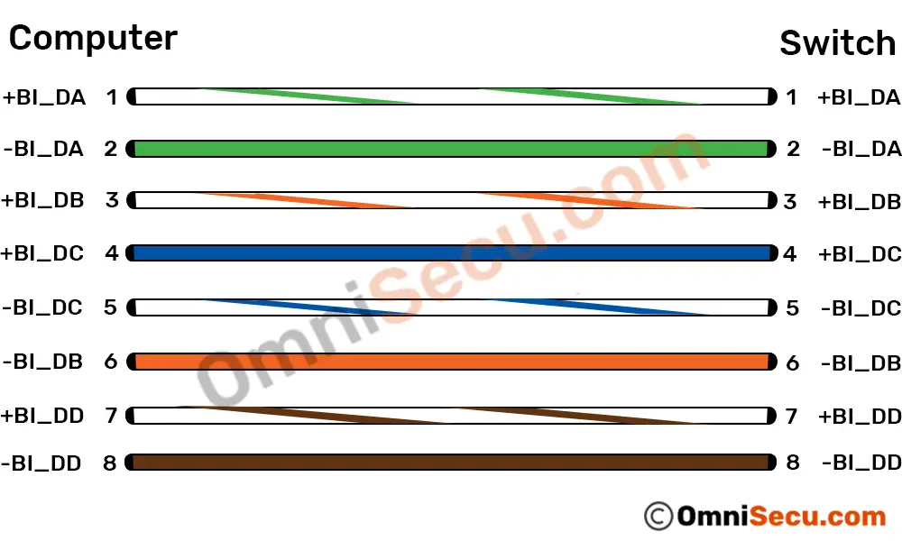
A graphical representation of above table of EIA/TIA 568A standard is copied below.
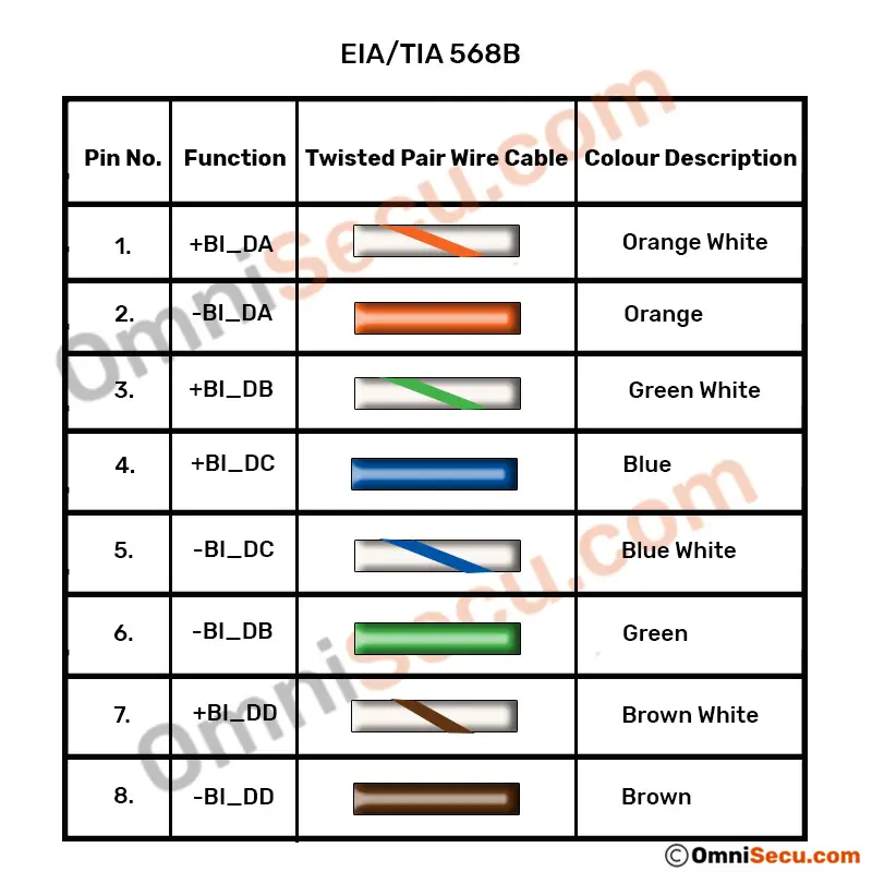
Please refer following table to learn Gigabit Ethernet cabling pinout, according to EIA/TIA 568B standard.
| Pin Number | Color | Function |
|---|---|---|
| 1 | Orange White | +BI_DA |
| 2 | Orange | -BI_DA |
| 3 | Green White | +BI_DB |
| 4 | Blue | +BI_DC |
| 5 | Blue White | -BI_DC |
| 6 | Green | -BI_DB |
| 7 | Brown White | +BI_DD |
| 8 | Brown | -BI_DD |
A graphical representation of above table of EIA/TIA 568B standard is copied below.