Search

What is Layer 2 Switching loop

In practical Local Area Networking, it is common that the switches are interconnected for redundancy. When switches are interconnected, the network will not fail completely even one if the connected link fails.

When switches are interconnected for redundancy as shown below, another serious network problem can occur, which is known as Layer 2 Switching loop.

The Layer 2 traffic can be classified as unicast (one to one), multicast (one to many), and broadcast (one to all). Unicasts, Multicasts and Broadcasts are different types of network communication and are required for the normal operation of the network. MAC addresses for broadcast and multicast are given below.

Broadcast Destination MAC address - FF:FF:FF:FF:FF:FFF

Multicast Destination MAC addresses - 01:00:5E:00:00:00 to 01:00:5E:7F:FF:FF

In case of a broadcast and multicast switch need to forward the Ethernet frame out all its ports.

For unknown destination MAC addresses also, the switch need to forward the packet to all ports (known as flooding) except the source port, to make sure that the Ethernet frame reach the destination.

To understand Layer 2 Switching loop, refer the following diagram.

Layer 2 Switching loop


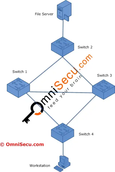
A Ethernet frame originating from Workstation to the File Server, first reaches the Switch 4. Switch 4 will forward the packet to all its ports (except the source port) since the MAC address of the destination device (File Server) may not be available in its MAC address table (File Server is attached to Switch 2).

Both Switch 1 and Switch 3 will receive a copy of the Ethernet frame . Now the Switch 1 and Switch 3 will search for the destination MAC address in its MAC address table and if they fail to find the destination MAC address in their MAC address tables, both the Switches will forward the Ethernet frame to all the ports (except the source port). This may cause the Ethernet frame to reach back the Switch 4 via path Switch 1 – Switch 3 – Switch 4 or Switch 3 – Switch 1 – Switch 4. This may lead to a switching loop and the Ethernet frame will start circulating the network in a loop.

Another problem is that the File Server can receive multiple copies of the same Ethernet frame arriving via different paths, which leads to additional overhead.

Layer 2 Switching loops may cause serious problem to network performance. Layer 2 Switching loops are prevented in networks using Spanning Tree Protocol.

Related Tutorials
• What is Broadcast Storm
• What is Layer 2 Switching loop
• What is Spanning Tree Protocol (STP)
• What is Bridge Protocol Data Unit (BPDU) frame
• Bridge Protocol Data Unit (BPDU) Frame Format
• What is a Root Bridge (Switch)
• What is a Root Port
• What are Port Cost, Port Priority and Path Cost Values
• How Spanning Tree Protocol (STP) select Root Port
• What is a Designated Port
• How Spanning Tree Protocol (STP) select Designated Port
• Difference between Root Port and Designated Port
• Spanning Tree Port States
• Topology Changes in Spanning Tree Protocol (STP)
• Spanning Tree Protocol (STP) Convergence
• What is Spanning Tree Protocol (STP) PortFast
• How to configure and verify Spanning Tree Protocol (STP) PortFast
• How to enable or disable Spanning Tree Protocol (STP)
• What is Rapid Spanning Tree Protocol (RSTP)
• Difference between Spanning Tree Protocol (STP) and Rapid Spanning Tree Protocol (RSTP)
• Per-VLAN Spanning Tree (PVST) and Per-VLAN Spanning Tree Plus (PVST+)
• What are Spanning Tree Bridge Priority and Bridge ID values
• Spanning Tree Path Cost Value and How is Spanning Tree Path Cost Value Calculated
• Spanning Tree Port Priority and Port ID Values
• How to change Spanning Tree Bridge Root Priority value and What is Extended System ID
• How to configure Spanning Tree Protocol Root Primary and Root Secondary
• What is a Root Bridge (Root Switch)
• How to change Spanning Tree Port Priority Value
• How Spanning Tree Protocol (STP) select Root Port
• What is a Designated Port
• How Spanning Tree Protocol (STP) select Designated Port
• Difference between Root Port and Designated Port
• Spanning Tree Port States
• How BPDU is generated and How BPDU works
• Important Spanning Tree Protocol (STP) Timers and their default values
• How to Configure and Change Spanning Tree Protocol (STP) Default Timer-Values for hello timer, forward delay timer and max age timer
• Topology Changes in Spanning Tree Protocol (STP)
• Spanning Tree Protocol (STP) Convergence
• Where to place the Spanning Tree Protocol Root Switch (Root Bridge)
• Spanning Tree Protocol (STP) UplinkFast, Backbone Fast and Portfast
• What is Spanning Tree Protocol (STP) Uplink Fast
• What is Spanning Tree Protocol (STP) Backbone Fast
• What is Spanning Tree Protocol (STP) PortFast
• How to configure and verify Spanning Tree Protocol (STP) PortFast
• How to enable or disable Spanning Tree Protocol (STP)
• What is Rapid Spanning Tree Protocol (RSTP)
• Difference between Spanning Tree Protocol (STP) and Rapid Spanning Tree Protocol (RSTP)
• Per-VLAN Spanning Tree (PVST) and Per-VLAN Spanning Tree Plus (PVST+)