Ethernet Frame Format
In this tutorial lesson, you will learn about Ethernet Frame format, Structure of Ethernet frame, Ethernet Frame header fields, Preamble, SFD (Start Frame Delimiter), Source and Destination MAC Addresses, Length, Data/Padding and FCS (Frame Check Sequence).
As you had learned from previous lessons, "Frame" is the name of data packet at layer 2 (Datalink layer) of five layered TCP/IP model. There are different formats available for Ethernet Frame. The format of most widely used Ethernet frame these days is explained below.
Structure of Ethernet Frame
The data packets from layer 3 (Network layer) is moved down to Layer 2 (Datalink Layer) as data moves down the TCP/IP protocol stack at Sender. There is a size limitation for Ethernet Frame. The total size of the ethernet frame must be between 64 bytes and 1,518 bytes (not including the preamble). Datalink layer breaks IP Datagrams (from Network layer) into smaller chunks (if necessary), which will become the data payload of ethernet frames at Datalink layer. A Frame includes data to be transmitted and also a header and a trailer which contain information that the network adapters on the ethernet need to process the frame.
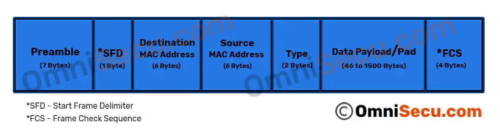
As you can see from below image (not including the preamble and SFD), the minimum size of an Ethernet Frame must be 64 bytes (6+6+2+46+4) and maximum size of an Ethernet Frame 1,518 bytes (6+6+2+1500+4).
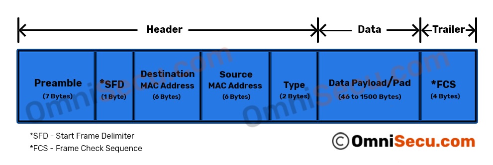
As you had learned from previous lessons, Ethernet "Frame" has a Header part, Data part and Trailer part. Please visit TCP/IP encapsulation and decapsulation lesson to learn more.
Following image shows the Header, Data and Trailer part of Ethernet Frame.
Ethernet Frame fields
Preamble
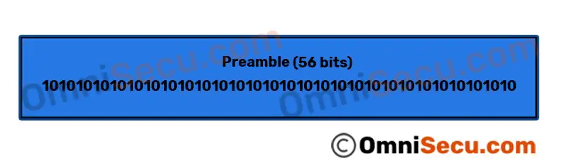
A sequence of 56 bits (7 bytes) having alternating 1 and 0 values (10101010101010101010101010101010101010101010101010101010) that are used for synchronization. Preamble allows receiving computer to synchronize timing and to reach a steady state before actual ethernet frame arrives.
SFD (Start Frame Delimiter)
SFD (Start Frame Delimiter) is a sequence of 8 bits having the bit configuration 10101011 that indicates the start of the frame. The difference between a Preamble byte and SFD byte is that the last bit of a Preamble byte is "0" (10101010) and last bit of SFD byte is "1" (10101011). The SFD (Start Frame Delimiter) byte indicates the receiving computer that the next part of Ethernet Frame transmission is the destination MAC address.

Source and Destination MAC Addresses
The Source MAC Address and the Destination MAC Address are the most important part of an ethernet frame. The Source MAC Address is the MAC Address of the device that the ethernet frame is coming from. The Destination MAC Address is the MAC Address of the device which is going to receive the ethernet frame. Both Source and Destination MAC Addresses fields are 6 bytes long.
MAC address (Layer 2 addresses, physical address or hardware address) is a universally unique identifier, permanently burned in the network card/interface. For Ethernet and Token Ring, these addresses are 48 bits, or six octets (bytes). MAC Addresses are represented in hexadecimal characters because hexadecimal format is easier for humans to read when compared with the binary format. One hexadecimal digit resembles a group of four contiguous binary bits, called a nibble. An example representation of MAC address is AA.F0.C1.E8.13.40.
To view the MAC Address when you are working with a Windows workstation, run cmd (Start > run > type cmd and Enter). Type the command "ipconfig /all" in the prompt and Enter. Do remember to remove double quotes.
Type
Type is a 2-byte (16-bit) field contains the information about the type of protocol at the upper layer of Layer 2 (Layer 3, Network Layer). Type field is used to identify the exact Layer 3 protocol at the receiving computer to which data packet is intended to be delivered.
Following table shows the hexadecimal codes of important Network Layer (Layer 3) protocols, used in Ethernet frame’s "Type field".
| Network Layer Protocol | Hexadecimal Code |
|---|---|
| IPv4 | 0x0800 |
| IPv6 | 0x86DD |
| IEEE 802.1Q (VLAN Tagged Frame) | 0x8100 |
| IEEE 802.1X (EAP over LAN) | 0x888E |
| ARP (Address Resolution Protocol) | 0x0806 |
| RARP (Reverse Address Resolution Protocol) | 0x8035 |
| Simple Network Management Protocol (SNMP) | 0x814C |
Data/Padding
This field contains the actual data transferred from the source device to the destination device. As you can see from Ethernet Frame format image, the minimum size of data field is 46 bytes and maximum size of data field is 1500 bytes.
Excluding preamble and SFD, the minimum Ethernet frame size is 64 bytes from the Destination MAC Address field including the Frame Check Sequence field. If the length of Data field is less than its minimum value (46 Bytes), then padding of "0’s" is added to meet the minimum allowed length.
FCS (Frame Check Sequence)
FCS (Frame Check Sequence) field contains a 4-byte Cyclic Redundancy Check (CRC) value used for error checking. When a source device assembles a frame, it performs a Cyclic Redundancy Check (CRC) calculation on all fields in the frame except the Preamble, SFD (Start Frame Delimiter), and frame check sequence using a predetermined algorithm. The source device stores the value in this field and transmits it as part of the frame. When the frame is received by the destination device, it performs an CRC test again using the same algorithm. If the CRC value calculated at the destination device does not match the value in the FCS (Frame Check Sequence) field, the destination device will discard the frame, considering this as a transmission error.
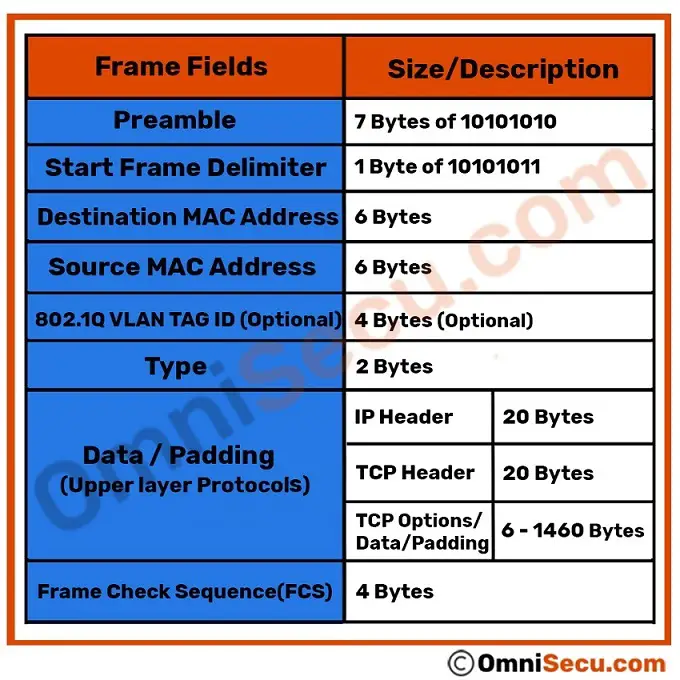
Following image shows Ethernet Frame fields and sizes, including upper layer protocol data.
Ethernet Runt and Giant Frames
The total size of the ethernet frame must be between 64 bytes and 1,518 bytes (not including the preamble). A frame shorter than the minimum 64 bytes but with a valid CRC is called as a runt. In most cases, such frames arise from a collision or a damaged network card. Any frame which is received and which is greater than the maximum frame size, is called a "giant". A "giant" is longer than 1518 bytes yet have a valid CRC. Both runts and giants are considered as invalid ethernet frames.
You have learned about Ethernet Frame format, structure of Ethernet Frame and different fields of Ethernet Frame. Click next link to continue learning.