Datalink Layer (Layer 2)
In this lesson, you will learn about datalink layer (layer 2) of TCP/IP network model.
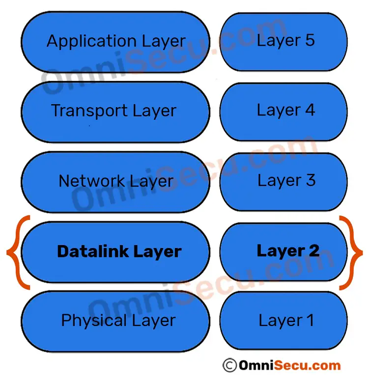
Layer 2 of TCP/IP model is the Datalink layer. Datalink layer is the second layer of TCP/IP model from the bottom. Datalink Layer is responsible for the encapsulation of outgoing IP Datagrams from Network layer (Layer 3) into Frames. Datalink Layer inserts a layer 2 header and also a layer 2 trailer to its upper layer data (Network Layer). Finally, Frames are sent over the network as bit stream at the physical layer to the destination computer.
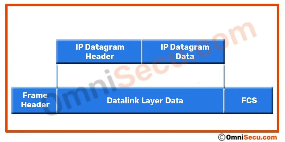
Datalink layer header contains information like source MAC Address and destination MAC Address. Datalink layer trailer contains a checksum value (FCS) for error detection.
The Datalink layer is again subdivided into the following two sub-layers according to their function:
Media Access Control (MAC) Sub-layer — MAC sub-layer provides an interface with the network adapter. Media Access Control (MAC) sublayer controls access to the network medium.
Logical Link Control (LLC) Sub-layer — LLC sub-layer is responsible for error-checking functions for frames delivered also responsible for managing links between communicating devices.
IP Datagrams generated at network layer (layer 3) are again encapsulated within an Ethernet Frame at datalink layer (layer 2), while moving down the TCP/IP protocol stack. Please refer below image to know how IP datagram packets are encapsulated within Ethernet Frame in Datalink layer. IP Datagrams are encapsulated within layer 2 header and trailer (FCS) as shown below
One of the most important functions of computer networking, "LAN Switching" is associated with Datalink Layer (Layer 2). LAN switching is a function of networking where the data packets (Frames) from one computer is transferred to another computer in a Local Area Network (LAN).
Please refer below image.
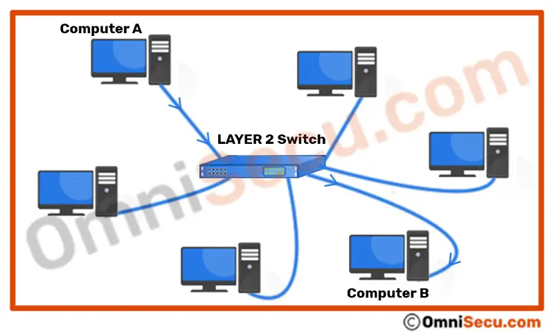
As we learned in previous lessons, computers inside a Local Area Network (LAN) are connected together by a network infrastructure device called "network Switch". If "Computer A" wants to send data to "Computer B", "Computer A" will place the data as bit stream over the network media. The bit stream is received by the Layer 2 Switch and the switch must now deliver the data to the intended recipient. This switch is also called as Layer 2 switch, because it operates at Layer 2 (datalink layer) of the TCP/IP model.
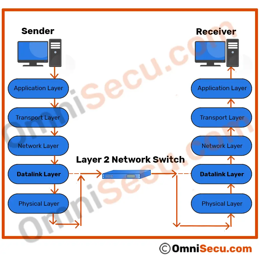
The simple meaning of the phrase "switch operates at Layer 2 (datalink layer)" is that the switch opens Datalink layer Frame header and trailer and use the information in the Frame header to deliver the Frame to the exact recipient computer (in above case, "Computer B").
A Layer 2 switch finds the destination device in a Local Area Network (LAN) (where the data to be delivered), by using the addresses at Datalink layer header. As you can see from the Datalink layer Frame format, the addresses inserted at the Datalink layer header are MAC addresses. MAC addresses are also called as Layer 2 addresses, physical address or hardware address.
Once again, MAC address (Layer 2 addresses, physical address or hardware address) are the addresses used by the LAN switches (at Datalink layer or Layer 2) to deliver Frames in a Local Area Network (LAN). Source and destination MAC addresses (Layer 2 addresses, physical address or hardware address) are found at Datalink layer packet, Frame header.
MAC address (Layer 2 addresses, physical address or hardware address) is a universally unique identifier, permanently burned in the network card. For Ethernet and Token Ring, these addresses are 48 bits, or six octets (bytes). MAC Addresses are represented as hexadecimal numbers because hexadecimal format is easier for humans to read when compared with the binary format. One hexadecimal digit resembles a group of four contiguous binary bits, called a nibble. An example representation of MAC address is AA.F0.C1.E8.13.40.
To view the MAC Address of your network card when you are using Windows Operating System, run command prompt, cmd (Right-click Start > Run > type cmd and click "OK"). Type the command "ipconfig /all" in the prompt and Enter. Do remember to remove double quotes.
To get more wider view about different layers of TCP/IP protocol stack and how they operate together, please visit and learn below lessons in order.
- Five layered TCP/IP model
- How data is moved through different layers of TCP/IP model at sending and receiving computers
- Name of data packets at different layers of TCP/IP model
- TCP/IP Encapsulation and Decapsulation
- Application Layer (Layer 5)
- Transport Layer (Layer 4)
- Network Layer (Layer 3)
- Datalink Layer (Layer 2)
- Physical Layer (Layer 1)
You have learned about Datalink layer of TCP/IP network model. Click next link to continue.