TCP/IP Encapsulation and Decapsulation
You will learn what is TCP/IP encapsulation and decapsulation, and how data is packed at different layers of TCP/IP protocol stack.
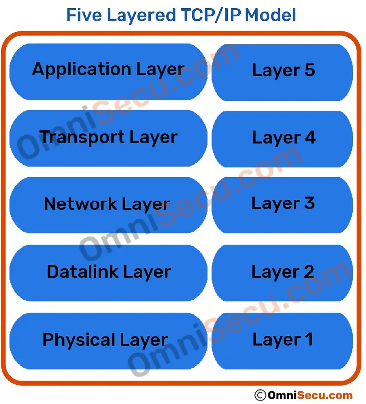
Before proceeding to learn the terms TCP/IP encapsulation and TCP/IP decapsulation, let us have a look at five layers of TCP/IP model.
TCP/IP Encapsulation
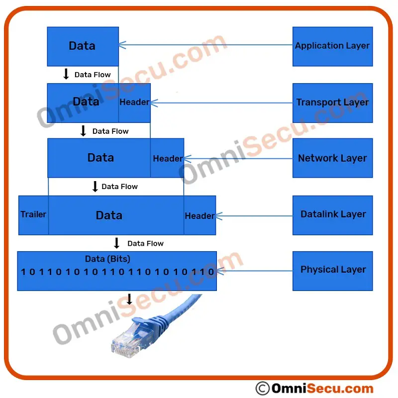
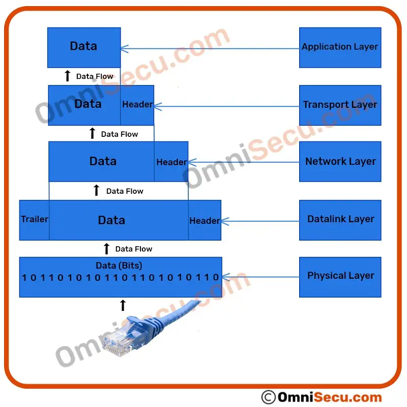
When data moves from upper layer to lower layer of TCP/IP protocol stack, during an outgoing transmission, each layer includes a bundle of relevant information called "header" along with the actual data. The data package containing the header and the data from the upper layer then becomes the data that is repackaged at the next lower level with lower layer's header. Header is the supplemental data placed at the beginning of a block of data when it is transmitted. This supplemental data is used at the receiving side to extract the data from the encapsulated data packet. This packing of data at each layer is known as data encapsulation.
TCP/IP Encapsulation
To visualize TCP/IP encapsulation process, refer below images.
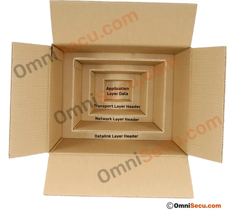
Let us imagine four carton boxes (used to pack items for sending via courier), smaller one placed inside the bigger one as shown below.
Application Layer (Layer 5)
Usually, the data for network transmission is generated at the Application layer. The data for network transmission from the Application layer is then encapsulated at its lower layer, Transport layer. Main protocols at Transport Layer are (TCP (Transmission Control Protocol) and UDP (User Datagram Protocol)).
The data generated at the Application layer for network transmission is called as "Message". The data generated at the Application layer (Layer 5) is then passed down to Transport layer. Following image is a visual representation of the data generated at Application layer.
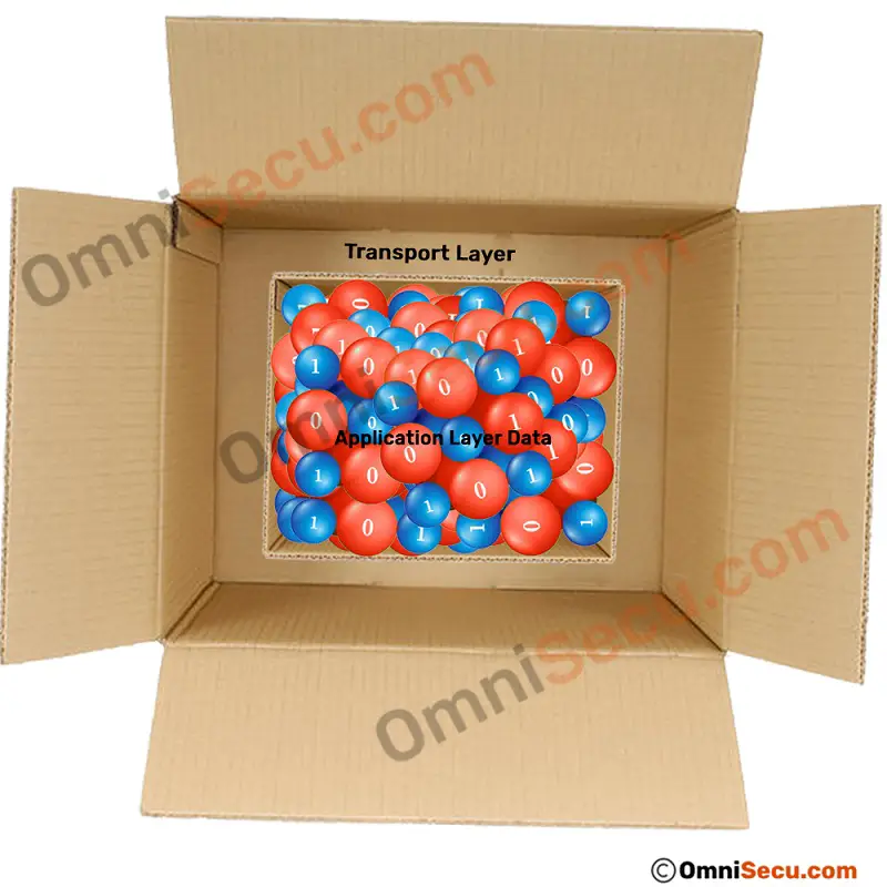
Transport Layer (Layer 4)
Transport layer adds many information with original data as Transport layer header (Layer 4 header), which are relevant for data processing at the Transport layer.
As described in the previous lesson, the Transport layer contains two important protocols: TCP (Transmission Control Protocol) and UDP (User Datagram Protocol). TCP (Transmission Control Protocol) is more reliable but consumes more resource. UDP (User Datagram Protocol) is less reliable but consume fewer resources than TCP (Transmission Control Protocol). UDP (User Datagram Protocol) is faster than TCP (Transmission Control Protocol).
The Application layer message is encapsulated at the Transport layer. If the protocol used at the Transport Layer is TCP (Transmission Control Protocol), the data packet is known as "TCP Segment". If the protocol used at the Transport layer is UDP (User Datagram Protocol), the data packet is known as "UDP Datagram".
The most important values at Transport layer header (Layer 4 header) are TCP/UDP source and destination port numbers. Data packet generated at Transport Layer (Layer 4) is then passed down to Network layer (Layer 3) for further processing. Following image represents the data packet generated at Transport layer.

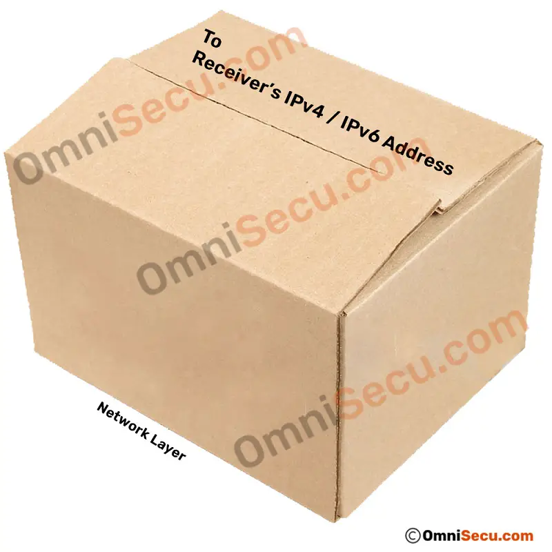
Network Layer (Layer 3)
Network layer adds additional data as header, which are relevant for processing data at Network layer.

The data packet created at the Network layer by Internet Protocol (IPv4 or IPv6), which encapsulates its upper layer Transport layer segment/datagram, is known as "IP Datagram".
The most important values at Network layer header (Layer 3 header) are source and destination IPv4/IPv6 addresses (Layer 3 addresses). The data packet generated at Network layer is then passed down to Datalink Layer (Layer 2). Following image represents data packet generated at the Network layer.
Datalink layer (Layer 2)
The data packet generated at Network layer is then placed inside Datalink layer header and trailer (Layer 2 header and trailer). Values inside Datalink layer header and trailer are relevant for processing data at Datalink layer.
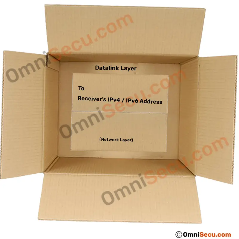
The data packet at the Datalink layer, which encapsulates and may subdivide the IP Datagram, is known as a "Frame" (generally Ethernet Frame).
The most important values at Datalink layer header (Layer 2 header) are source and destination MAC addresses (Layer 2 addresses). Following image represents data packet generated at Datalink layer.

Physical Layer (Layer 1)
The Frame is then transferred to Physical Layer (Layer 1), and is converted into stream of bits at the Physical layer (Layer 1). The stream of bits is then placed on network medium for transmission to the destination computer.
TCP/IP Decapsulation
The reverse process of encapsulation (or decapsulation) occurs when data is received on the destination computer during an incoming transmission. As the data moves up from the lower layer to the upper layer of TCP/IP protocol stack (incoming transmission), each layer unpacks the corresponding header and uses the information contained in the header to deliver the packet to the exact network application waiting for the data.
TCP/IP Decapsulation
Physical Layer (Layer 1)
Stream of bits are picked from network medium and then transferred to its upper layer, which is Datalink layer (Layer 2).
Datalink Layer (Layer 2)
Receiver opens the Datalink layer header and trailer (Layer 2 header and trailer), uses the values at Datalink header and trailer for processing data at the Datalink layer.
Receiver then collects the Network layer packet (IPv4 or IPv6 Datagram), and it is transferred to Network layer for further processing.
Network Layer (Layer 3)
Receiver opens the Network layer header (Layer 3 header), uses the values at Network layer header (Layer 3 header) for processing data at Network layer.
Receiver then collects the Transport layer packet (TCP or UDP), and it is transferred to Transport layer for further processing.
Transport Layer (Layer 4)
Receiver opens the Transport layer header (Layer 4 header), uses the values at Transport layer header (Layer 4 header) for processing data at the Transport layer.
Receiver then collects the Application layer data, and it is transferred to the Application layer for the network application waiting for incoming network data.
Screenshot of an encapsulated Ethernet frame
Let us have a look at an encapsulated Ethernet frame, carrying HTTPS protocol (HyperText Transfer Protocol - Secure) data from a web server to the client. You can see from the Wireshark packet capture screenshot that where Datalink layer, Transport layer, Network layer and Application layer areas are marked.
As explained earlier in this lesson, you can see the source and destination MAC addresses at Datalink layer, source and destination IP addresses at Network layer and source and destination port numbers at Transport layer. Also note that the source port number is 443, which is the well-known port number for HTTPS. You can also see the encrypted Application layer data, at the bottom of the screenshot.

Note: The first octet of the source IPv4 address in above Wireshark packet capture screenshot is hidden to protect third-party web server.
To get more wider view about different layers of TCP/IP protocol stack and how they operate together, please visit and learn below lessons in order.
- Five layered TCP/IP model
- How data is moved through different layers of TCP/IP model at sending and receiving computers
- Name of data packets at different layers of TCP/IP model
- TCP/IP Encapsulation and Decapsulation
- Application Layer (Layer 5)
- Transport Layer (Layer 4)
- Network Layer (Layer 3)
- Datalink Layer (Layer 2)
- Physical Layer (Layer 1)
In this lesson, you have learned what is TCP/IP Encapsulation and Decapsulation. Click below links to move to previous or next lessons.