IPv4 Protocol, IPv4 header and fields of IPv4 header
IPv4 Protocol (Internet Protocol - Version 4)
The IPv4 Protocol implements two basic functions of network traffic; 1) Logical addressing / Routing of IPv4 datagram packets and 2) Fragmentation and Reassembly of IPv4 Datagrams.
1) Logical addressing / Routing of IPv4 datagram packets: Routing is the process of selecting best path / paths in a network along which to send the IPv4 datagrams efficiently. The Network Layer uses the IPv4 addresses (also called as logical addresses) for communication. IPv4 addresses (also called as logical addresses) are 32-bit binary numbers represented in 4 octets (or bytes). If you are using IPv4 in your network (another choice is IPv6), Routers use IPv4 addresses to route IPv4 datagrams from one LAN to another LAN.
2) Fragmentation and Reassembly of IPv4 Datagrams: To understand what is IPv4 Datagram Fragmentation, first we should know the term MTU (Maximum Transmission Unit). MTU is the size (in bytes) of the largest packet or frame that can pass through a specific device or NIC card. While travelling through the network to reach the destination, the Internet Protocol Version 4 (IPv4) datagrams may need to traverse different networks with heterogeneous MTUs. When a datagram is larger than the MTU of the network it needs to traverse, it is divided into smaller fragments and are sent separately. At the destination computer the fragmented IPv4 Datagram is reconstructed and this process in called reassembly.
More about Fragmentation and Reassembly of IPv4 packets are explained at the bottom part of this tutorial lesson.
IPv4 Header
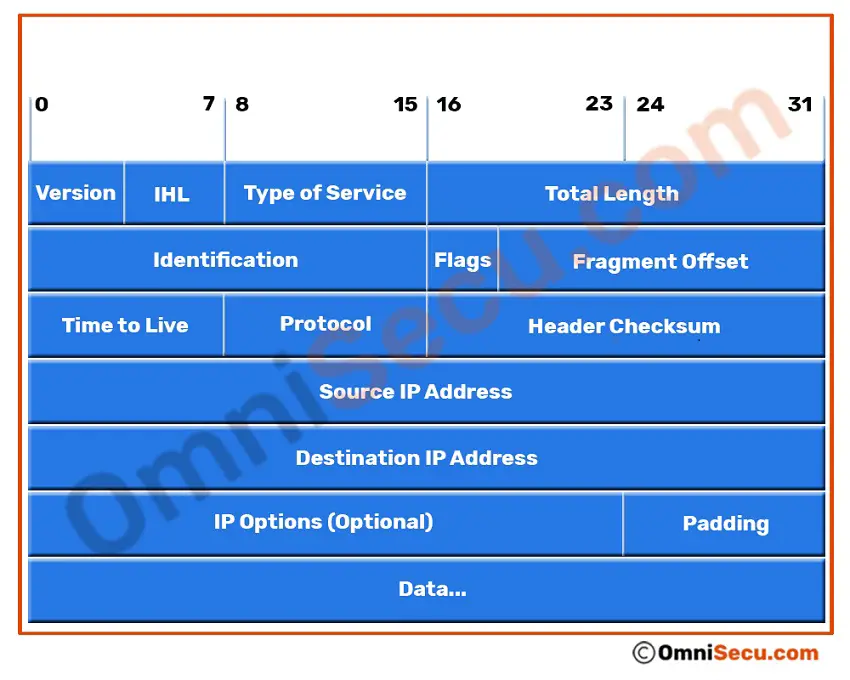
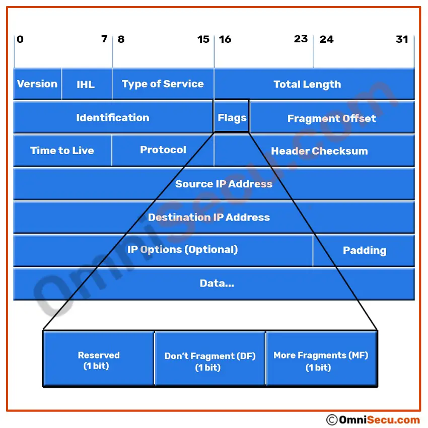
Following image shows the structure and the fields of IPv4 header.
"Version" field of IPv4 header
"Version" is 4-bit field indicates which version of Internet Protocol (IP) is being used. Here we are discussing about IPv4. The binary pattern for IPv4 is 0100. The possible values for Version field are as shown in the table below. IPv4 is moving away slowly from industry for IPv6.
| IP Version | Description |
|---|---|
| 0 | Reserved |
| 1-3 | Unassigned |
| 4 | IP Version 4 |
| 5 | Stream IP Datagram mode (experimental protocol) |
| 6 | IP Version 6 |
| 7 | TP/IX |
| 8 | The "P" internet protocol |
| 9 | TUBA |
| 10-14 | Unassigned |
| 15 | Reserved |
Note: The TP/IX, "P" Internet protocol, and TUBA were the major protocols considered for the replacement of IPv4, but the industry embraced "IP Version 6" as the replacement for "IP Version 4" all other protocols mentioned above only have historical status.
"IHL (Internet Header Length)" field of IPv4 header
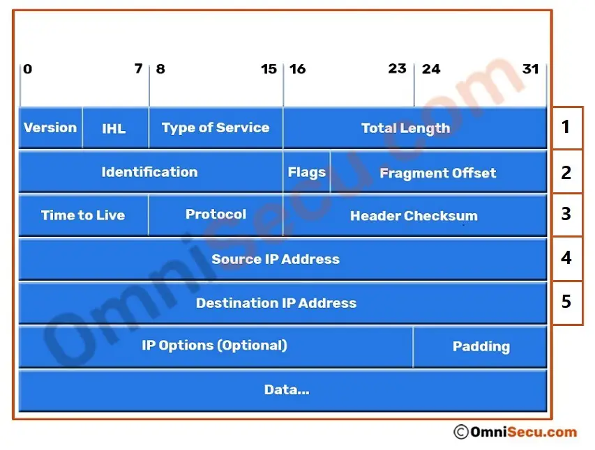
"IHL (Internet Header Length)" field is 4-bits long binary number. This 4-bit IHL (Internet Header Length) field gives the "length of IPv4 header" in 32-bit words. Since IHL (Internet Header Length) is a 4-bit binary number, IHL field in IPv4 header can hold values from 0000 (0 in decimals) to 1111 (15 in decimals). Minimum required field size of IPv4 header is 20 bytes. Minimum required length of an IPv4 header is five 32-bit words (5*32 = 160 bits or 20 bytes). The length of required fields in IPv4 header is 20 bytes. Maximum possible is fifteen 32-bit words (15*32 = 480 bits or 60 bytes). The bit pattern of is IHL field in IPv4 header is 0101, which is equal to five in decimals.
Please refer below image to understand the meaning of 32-bit words of IPv4 header. Numbered at right-side are the required fields of IPv4 header.
"Type of Service (ToS)" field of IPv4 header
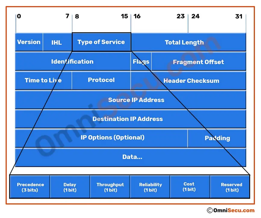
The "Type of Service (ToS)" field in the Internet Protocol (IPv4) header is an eight-bit length binary number field, which provides an indication of the Quality of Service (QoS) desired, such as precedence, delay, throughput, and reliability.
By using Quality of Service (QoS), network administrators can prioritize specific types of traffic on the network to provide better user experience. QoS (Quality of Service) can be used to manage network traffic with different priority levels for different types of traffic. QoS (Quality of Service) can be used prioritize resource-intensive traffic like Voice over IP (VoIP), Online Gaming, Video Conferencing, IP Television (IPTV) etc.
Please refer two images placed below to view a graphical represntation of 8-bit "Type of Service (ToS)" field in IPv4 header.
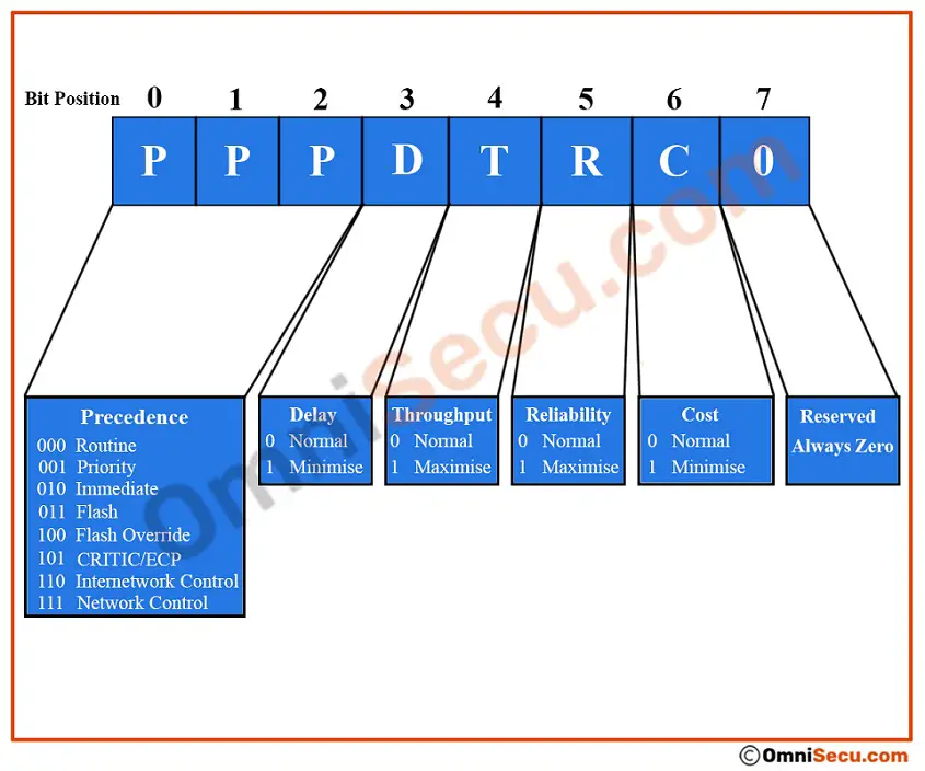
The first three bits (0 to 2) of "Type of Service (ToS)" field in IPv4 header indicates the "Precedence" value. The following are the possible combinations for the first three bits (0 to 2) of "Type of Service (ToS)" field in IPv4 header.
| Bits Pattern | Description |
|---|---|
| 000 | Routine |
| 001 | Priority |
| 010 | Immediate |
| 011 | Flash |
| 100 | Flash Override |
| 101 | CRITIC/ECP |
| 110 | Internetwork Control |
| 111 | Network Control |
The fourth bit indicates "Delay". The bit value “0” indicates normal delay and the bit value "1" indicate low delay.
The fifth bit indicates "Throughput". The bit value “0” indicates normal throughput and the bit value "1" indicate high throughput.
The sixth bit indicate "Reliability". The bit value “0” indicates normal reliability and the bit value "1" indicate high reliability.
The seventh bit indicates "Cost". The bit value "0" indicates "normal monetary cost" and the bit value "1" indicates "minimize monetary cost".
The eight bit is reserved for future use and is termed as MBZ (Must be Zero)
The four bits which represent the ToS values can be summarized as below.
| ToS Code | Meaning |
|---|---|
| 1000 | Minimum Delay |
| 0100 | Maximum throughput |
| 0010 | Maximum Reliability |
| 0001 | Minimum monetary cost |
| 0000 | Normal Service |
"Total Length" field of IPv4 header
The "Total Length" in IPv4 header is a 16-bit field which identifies the length (in bytes), of the IPv4 datagram. Total Length includes the length of IPv4 header and the Data it carries. The minimum-length of an IPv4 Datagram is 20 bytes (The minimum size of an IP header is 20 bytes and this is the case of an IPv4 header carrying no data) and the maximum is 65,535 bytes (maximum possible value for a 16-bit number is 65,535).
"Identification" field of IPv4 header
The "Identification" field in the IPv4 header is a 16 bits field which indicates an identifying value assigned by the sender to aid in assembling the fragments of an IPv4 Datagram. When a Datagram is fragmented in to multiple Datagrams, IPv4 give all the fragments the same identification number and this number is used to identify IPv4 fragments at the receiving side. More about IPv4 fragmentation is given below.
"Flags" field of IPv4 header
The three bit "Flags" field in IPv4 header indicates fragmentation possibilities. The first bit is unused and should always have a value of zero. The next bit is called the DF (Don't Fragment) flag. DF flag set to "0" indicate that the IPv4 Datagram can be fragmented and DF set to 1 indicate "Don't Fragment" the IPv4 Datagram. The next bit is the MF (More Fragments) flag, which indicates that more fragments are on the way. When MF is set to 0, no more fragments need to be sent or the IPv4 Datagram was never fragmented.
Please refer below image to view a graphical represntation of 3-bit "Flags" field in IPv4 header.
"Fragment Offset" field of IPv4 header
"Fragment Offset" field of IPv4 header indicates where in the actual IPv4 Datagram this fragment belongs. The fragment offset is measured in units of 8 octets (64 bits). The first fragment has offset zero. To understand what is IPv4 fragmentation, refer below image.
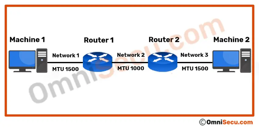
IPv4 Datagram Fragmentation
Network 1 and Network 3 has MTUs of 1500 bytes each and the MTU of Network 3 is only 1000 bytes. If Machine 1 sends a 1,500 byte Datagram (20-byte header and 1,480 bytes of data) to Machine 2, Router 1 must fragment the Datagram into two fragments, since the MTU for the Network 2 is only 1000 bytes.
1) The first fragment will contain 20 bytes IPv4 header and 976 bytes of data. Also note that the Fragment offset is set to "0" (Since first fragment) and the MF (More Fragments) flag is set to "1".
2) The second fragment will contain a 20 byte IPv4 header and 504 bytes of data. The fragment offset is set to 122 (976/8 = 122) and the MF (More Fragments) flag is set to "0". When the IPv4 Datagram is fragmented to two, there is an additional 20 bytes of transfer which is the IPv4 Datagram header size of the second fragment.
"Time to Live (TTL)" field of IPv4 header
"Time to Live (TTL)" is an 8-bit field and Time to Live (TTL) indicates the amount of time in seconds (or router hops) that the IPv4 Datagram can survive before being discarded. Every router examines and decrements this field by at least 1, or by the number of seconds the IPv4 Datagram is delayed inside the router. The Internet Protocol Version 4 (IPv4) Datagram is discarded when this field reaches zero.
In computer networking, Time to Live (TTL) field value is typically used to prevent routing loops.
"Protocol" field of IPv4 header
The 8-bit "Protocol" field indicates the protocol that will receive the data payload. For example, ICMP (Internet Control Message Protocol) has a Protocol number of 1, TCP (Transmission Control Protocol) has a Protocol number of 6, UDP (User Datagram Protocol) has a Protocol number of 17, RDP (Reliable Data Protocol) has a Protocol number of 27, ESP (Encapsulating Security Payload) has a Protocol number of 50 etc.
The Protocol field in IPv4 header is used to demultiplex an IPv4 packet to a Transport layer (Layer 4) protocol. Following table lists important Protocol numbers. You may find latest Protocol Number Assignments from IANA Protocol Number Assignments page.
| Field Value | Protocol Description |
|---|---|
| 0 | IPv6 Hop-by-Hop Option. |
| 1 | ICMP (Internet Control Message Protocol) |
| 2 | IGMP (Internet Group Management Protocol) RGMP (Router-port Group Management Protocol) |
| 3 | GGP (Gateway to Gateway Protocol) |
| 4 | IPv4 in IP encapsulation |
| 5 | ST (Internet Stream Protocol) |
| 6 | TCP (Transmission Control Protocol) |
| 7 | CBT (Core Based Trees) |
| 8 | EGP (Exterior Gateway Protocol) |
| 9 | IGRP (Interior Gateway Routing Protocol - Cisco) |
| 10 | BBN- RCC-MON (BBN RCC Monitoring ) |
| 11 | NVP (Network Voice Protocol) |
| 12 | Xerox PUP |
| 13 | ARGUS (deprecated) |
| 14 | EMCON (Emission Control Protocol) |
| 15 | XNET Cross Net Debugger |
| 16 | Chaos (Chaosnet) |
| 17 | UDP (User Datagram Protocol) |
| 18 | TMux (Transport Multiplexing Protocol) |
| 19 | DCN Measurement Subsystems |
| 20 | HMP (Host Monitoring Protocol) |
| 21 | Packet Radio Measurement |
| 22 | XEROX NS IDP |
| 23 | Trunk-1 |
| 24 | Trunk-2 |
| 25 | Leaf-1 |
| 26 | Leaf-2 |
| 27 | RDP (Reliable Data Protocol) |
| 28 | IRTP (Internet Reliable Transaction Protocol) |
| 29 | ISO Transport Protocol Class 4. |
| 30 | NETBLT (Network Block Transfer) |
| 31 | MFE Network Services Protocol |
| 32 | MERIT Internodal Protocol |
| 33 | Sequential Exchange Protocol |
| 34 | Third Party Connect Protocol |
| 35 | IDPR (Inter-Domain Policy Routing Protocol) |
| 36 | XTP (Xpress Transfer Protocol) |
| 37 | Datagram Delivery Protocol |
| 38 | IDPR-CMTP (IPDR Control Message Transport Protocol) |
| 39 | TP++ (TP++ Transport Protocol) |
| 40 | IL Transport Protocol |
| 41 | IPv6 over IPv4 (6in4) |
| 42 | SDRP (Source Demand Routing Protocol) |
| 43 | IPv6 Routing header |
| 44 | IPv6 Fragment header |
| 45 | IDRP (Inter-Domain Routing Protocol) |
| 46 | RSVP (Reservation Protocol) |
| 47 | GRE (General Routing Encapsulation) |
| 48 | MHRP (Mobile Host Routing Protocol) |
| 49 | BNA (Burroughs Network Architecture) |
| 50 | ESP (Encapsulating Security Payload) |
| 51 | AH (Authentication Header) |
| 52 | Integrated Net Layer Security TUBA |
| 53 | SWIPE (IP with Encryption (deprecated)) |
| 54 | NARP (NBMA Address Resolution Protocol) |
| 55 | Minimal Encapsulation Protocol |
| 56 | TLSP (Transport Layer Security Protocol using Kryptonet key management) |
| 57 | SKIP (Simple Key-Management for Internet Protocol) |
| 58 | ICMPv6 (Internet Control Message Protocol for IPv6) MLD (Multicast Listener Discovery) |
| 59 | IPv6 No Next Header |
| 60 | Destination Options for IPv6 |
| 61 | Any host internal protocol |
| 62 | CFTP |
| 63 | Any local network |
| 64 | SATNET and Backroom EXPAK |
| 65 | Kryptolan |
| 66 | MIT Remote Virtual Disk Protocol |
| 67 | Internet Pluribus Packet Core |
| 68 | Any distributed file system |
| 69 | SATNET Monitoring |
| 70 | VISA Protocol |
| 71 | Internet Packet Core Utility |
| 72 | Computer Protocol Network Executive |
| 73 | Computer Protocol Heart Beat |
| 74 | Wang Span Network |
| 75 | Packet Video Protocol |
| 76 | Backroom SATNET Monitoring |
| 77 | SUN ND PROTOCOL-Temporary |
| 78 | WIDEBAND Monitoring |
| 79 | WIDEBAND EXPAK |
| 80 | ISO Internet Protocol |
| 81 | VMTP (Versatile Message Transaction Protocol) |
| 82 | SECURE-VMTP |
| 83 | VINES |
| 84 | TTP |
| 85 | NSFNET-IGP |
| 86 | Dissimilar Gateway Protocol |
| 87 | TCF |
| 88 | EIGRP (Enhanced Interior Gateway Routing Protocol - Cisco) |
| 89 | OSPF (Open Shortest Path First Routing Protocol) MOSPF (Multicast Open Shortest Path First) |
| 90 | Sprite RPC Protocol |
| 91 | Locus Address Resolution Protocol |
| 92 | MTP (Multicast Transport Protocol) |
| 93 | AX.25 (AX.25 Frames) |
| 94 | IPIP (IP-within-IP Encapsulation Protocol) |
| 95 | MICP (Mobile Internetworking Control Protocol, depricated) |
| 96 | SCC-SP (Semaphore Communications Sec. Pro.) |
| 97 | ETHERIP (Ethernet-within-IP Encapsulation) |
| 98 | ENCAP (Encapsulation Header) |
| 99 | Any private encryption scheme |
| 100 | GMTP |
| 101 | IFMP (Ipsilon Flow Management Protocol) |
| 102 | PNNI over IP |
| 103 | PIM (Protocol Independent Multicast) |
| 104 | ARIS (Aggregate Route IP Switching Protocol) |
| 105 | SCPS |
| 106 | QNX |
| 107 | A/N (Active Networks) |
| 108 | IPComp (IP Payload Compression Protocol) |
| 109 | SNP (Sitara Networks Protocol) |
| 110 | Compaq-Peer (Compaq Peer Protocol) |
| 111 | IPX-in-IP (IPX in IP) |
| 112 | VRRP (Virtual Router Redundancy Protocol) |
| 113 | PGM (PGM Reliable Transport Protocol) |
| 114 | any 0-hop protocol |
| 115 | L2TP (Level 2 Tunneling Protocol) |
| 116 | DDX (D-II Data Exchange) |
| 117 | IATP (Interactive Agent Transfer Protocol) |
| 118 | STP (Schedule Transfer Protocol) |
| 119 | SRP (SpectraLink Radio Protocol) |
| 120 | UTI (Universal Transport Interface Protocol) |
| 121 | SMP (Simple Message Protocol) |
| 122 | SM (Simple Multicast Protocol) |
| 123 | PTP (Performance Transparency Protocol) |
| 124 | ISIS over IPv4 |
| 125 | FIRE (Flexible Intra-AS Routing Environment ) |
| 126 | CRTP (Combat Radio Transport Protocol) |
| 127 | CRUDP (Combat Radio User Datagram) |
| 128 | SSCOPMCE (Service-Specific Connection-Oriented Protocol in a Multilink and Connectionless Environment) |
| 129 | IPLT |
| 130 | SPS (Secure Packet Shield) |
| 131 | PIPE (Private IP Encapsulation within IP) |
| 132 | SCTP (Stream Control Transmission Protocol) |
| 133 | Fibre Channel |
| 134 | RSVP-E2E-IGNORE |
| 135 | Mobility Header |
| 135 | Mobility Header |
| 137 | MPLS-in-IP |
| 144 - 252 |
Unassigned |
| 253 | Testing |
| 254 | Testing |
| 255 | Reserved |
"Header Checksum" field of IPv4 header
The "Header Checksum" field holds a 16-bit calculated value to verify the validity of the header only. This field is recomputed in every router as the TTL field decrements.
"Source and Destination IPv4 Address" fields of IPv4 header
Source and Destination IPv4 Address fields are the most important fields of IPv4 header.
The "Source IP Address" is the 32-bit size IPv4 address of the device which sends this Internet Protocol (IPv4) Datagram.
The "Destination IPv4 Address" is the 32-bit size IPv4 address of the device which is going to receive this IPv4 Datagram.
"IP Options" field of IPv4 header
"IP Options" field supports a number of optional header settings primarily used for testing, debugging, and security.
"Padding" field of IPv4 header
The IPv4 Options field may vary in length. The "Padding" field provides additional zero bits so that the total header length is an exact multiple of 32 bits.
"Data"
"Data" is the real IPv4 data payload and the actual size may vary. Data is not a part of the IPv4 header and it contains data generated by other protocols like TCP, UDP, ICMP, IGMP etc.
You have learned Internet Protocol Version 4 (IPv4), Internet Protocol Version 4 (IPv4) Datagram Header, different fields in an IPv4 header, and IPv4 Datagram fragmentation. The different fields of an IPv4 header are Version, IHL, Type of Service, Total Length, Flags, Fragment offset, TTL (Time to Live), Protocol, Header Checksum, Source IPv4 Address, Destination IPv4 Address, IP Options, Padding and the Data Payload. Click "Next" link below to continue.