How IPv4 multicast works on Ethernet
We have learned the concepts of multicast in many of the previous lessons. In this lesson, we will learn how IPv4 multicast works on Ethernet.
Before continuing further, I suggest you to visit and learn following lessons.
- Unicast, Multicast and Broadcast
- Broadcast domain
- Datalink layer of TCP/IP model
- Ethernet Frame Format
- MAC addresses
- Broadcast MAC Address - ff:ff:ff:ff:ff:ff
- IPv4 multicast MAC Addresses
- Network layer of TCP/IP model
- IPv4 Protocol, IPv4 header and fields of IPv4 header
- IPv4 addresses
- Class D multicast IP addresses
- Multicast IPv4 address to MAC address mapping
- What is limited broadcast in IPv4 and how limited broadcast works
- What is directed broadcast in IPv4 and how directed broadcast works
- Transport layer of TCP/IP model
- TCP/IP Encapsulation and Decapsulation
- What is multicast
- What is multicast group
- Advantages and disadvantages of multicast
- How IPv4 multicast works on LAN
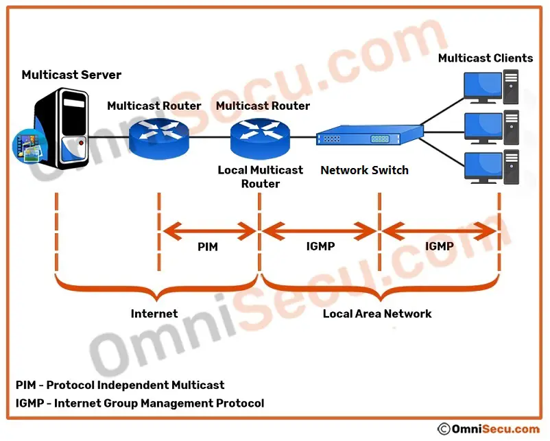
There are two protocols mainly involved in IPv4 multicasting; IGMP and PIM. Let us keep aside IGMP and PIM for deep learning in future lessons. But, short explanations about IGMP and PIM are in below paragraphs.
IGMP (Internet Group Management Protocol) is an integral protocol of TCP/IP protocol suite which allows a computer to advertise its multicast group membership in Local Area Network (LAN), especially to local multicast routers. In other words, IGMP is used by a computer in a Local Area Network (LAN) to inform the local multicast router that it is interested in receiving multicast traffic from a specific multicast group.
PIM (Protocol Independent Multicast) is a multicast routing protocol that advertises multicast sources and receivers in a routed layer 3 network.
Please refer below image.
For the purpose of this lesson (learning how IPv4 multicast works on LAN), let us concentrate on the LAN portion of the above image. LAN portion of the above image is copied below. Note that all the traffic to the multicast router must pass via network switch.
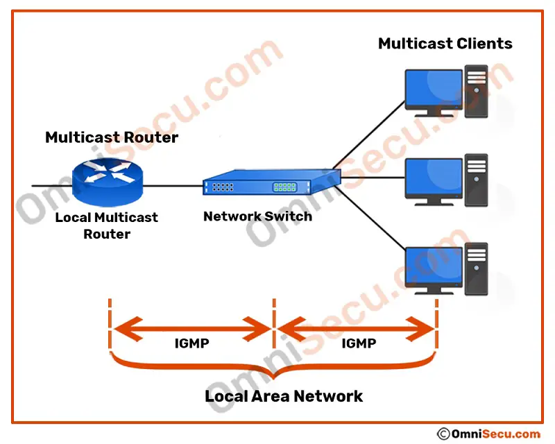
If computers on a LAN are interested to receive multicast traffic (Online TV, Video conferencing, Operating System deployment using images etc.) from a multicast group, computers use IGMP protocol to inform the multicast router about multicast group membership. For example; if a computer wants to receive an online TV video stream, it sends an IGMP message to the local multicast router that it is interested in receiving multicast packets sent to the related multicast group. Computers send IGMP Membership Report (MR) messages when they first join a multicast group. IGMP Membership Report (MR) messages are also sent in response to IGMP membership queries sent by routers. IGMP membership queries are sent from multicast routers to discover the presence of group members on a subnet.
IGMP is used on IPv4 networks. IPv6 has different set of protocols for multicast. There are three versions of IGMP; IGMPv1, IGMPv2 and IGMPv3. As mentioned above, "Membership Report (MR)" type of IGMP message is used by multicast clients to join a multicast group. "Membership Report (MR)" messages are also used to respond to a local multicast router’s Membership Query messages. If a multicast client wants to join a particular multicast group, it will send a IGMPv3 Membership Report (MR) message to link-local multicast address 224.0.0.22. Class D IPv4 address 224.0.0.22 is the link-local multicast IPv4 address to which all IGMPv3 capable routers listen.
Please refer below image. Here in this example, let us assume that two computers with IPv4 address 192.168.10.101 and 192.168.10.102 want to receive multicast traffic sent to the multicast group 239.10.10.10. To receive multicast traffic sent to the multicast group 239.10.10.10, two computers need to join the multicast group. To join the multicast group, two computers must inform the local multicast router that they are interested to join multicast group 239.10.10.10 by sending IGMP join messages.
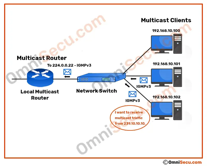
Please note that in this example we are using IGMPv3. IGMPv3 doesn’t have a separate join group message. To join the multicast group 239.10.10.10, the client computers (192.168.10.101 and 192.168.10.102) need to send IGMPv3 Membership Report (MR) message to the local multicast router at link-local multicast IPv4 address 224.0.0.22. IGMPv3 join message is a Membership Report (MR) message type with an empty EXCLUDE list. So, what is this EXCLUDE list? IGMPv3 has support for source filtering. EXCLUDE list is the list of IPv4 addresses from which the clients do not want to receive multicast traffic.
Once again, 224.0.0.22 is the link-local multicast IPv4 address to which all IGMPv3 capable routers listen.
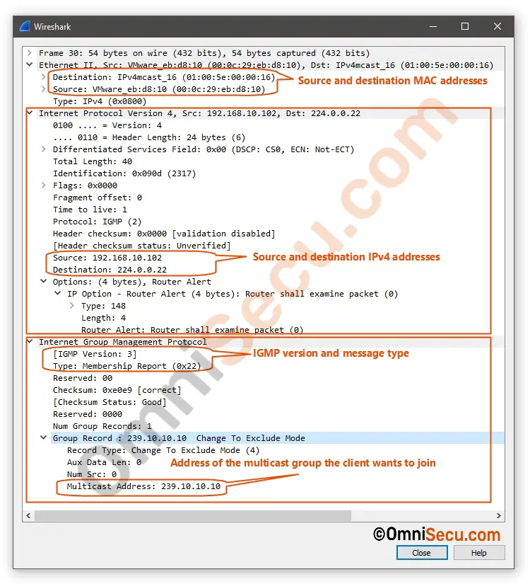
The Wireshark capture screenshot of IGMPv3 Membership Report (MR) join message sent to destination multicast IPv4 address 224.0.0.22 is copied below. In this example, I am using IGMPv3 to send Membership Report (MR) message. If you are using any other version of IGMP, the captured packet may look different. We will learn about IGMP deep in coming TCP/IP lessons.
You can see from the below Wireshark capture screenshot, IGMPv3 Membership Report (MR) message is encapsulated in IPv4 datagram. The destination IPv4 address is 224.0.0.22. The destination MAC address is 00:01:5e:00:00:16. As learned from the previous lesson, 00:01:5e:00:00:16 is the mapped multicast MAC address for multicast IPv4 address 224.0.0.22. "Multicast Address" at the bottom of screenshot image is the address of the multicast group being reported.
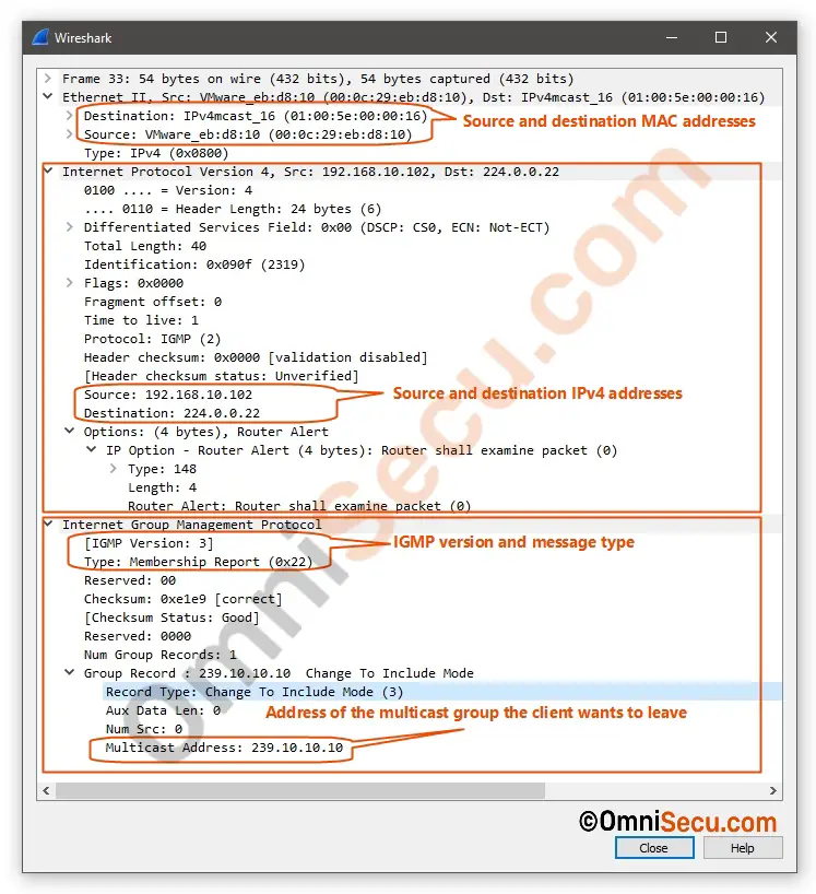
IGMPv3 Membership Report (MR) messages are also used to leave a multicast group. IGMPv3 Membership Report (MR) message with empty INCLUDE list is the leave message. INCLUDE list is the list of IPv4 addresses from which the computers want to receive multicast traffic. Wireshark packet capture screenshot of IGMPv3 leave message is also copied below for your reference.
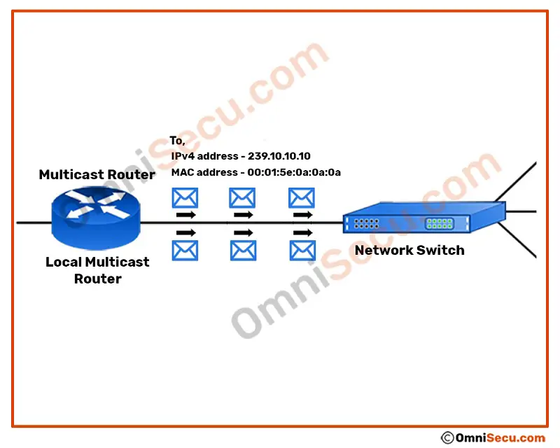
Now, the local multicast router needs to connect to the multicast server and start sending the multicast Ethernet frames to the two computers inside the LAN who joined the multicast stream. When the router starts sending multicast packets to the LAN, what will be the destination IPv4 address and MAC address of the multicast packets?
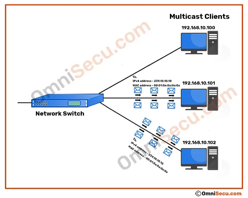
You guessed it correct; Destination IPv4 address of the multicast packets will be 239.10.10.10 and the destination MAC address of the multicast packets will be 00:01:5e:0a:0a:0a. The destination IPv4 address 239.10.10.10 is the multicast IPv4 address of the joined multicast group. But why the destination MAC address is 00:01:5e:0a:0a:0a? Destination MAC address 00:01:5e:0a:0a:0a is the mapped multicast MAC address for IPv4 multicast address 239.10.10.10. Refer below image.
The multicast Ethernet frames from the local multicast router have reached the network switch now. Remember, switches operate at layer 2 and they deliver Ethernet frames to computers inside a Local Area Network (LAN) based on the destination MAC address in Ethernet frame header. Now, the switch needs to deliver these multicast Ethernet frames to computers who joined the multicast group. For unicast type of network communication, switch identifies the port (interface) to which a computer is connected by looking at its MAC address table. MAC address table contains switch port (interface) identification number and the connected computer’s MAC address mapping entries. Switch populates and updates its MAC address table by watching incoming Ethernet frames via its switch ports (interfaces) and mapping the port number with source MAC address of incoming Ethernet frames. Since the multicast MAC addresses are used to represent a group of network interfaces, normally they appear as the destination MAC address in an Ethernet frame, not as the source MAC addresses.
In this case, the incoming Ethernet frame from the local multicast router is not for unicast type of delivery. The network switch can identify the incoming Ethernet frame is for multicast type of delivery from the destination multicast MAC address prefix 01:00:5e. For a "low-cost, feature-less" switch, it has is no other option, but to treat the multicast packets as broadcast packets. That means, flood it (or broadcast) to all the connected ports (except the incoming port).
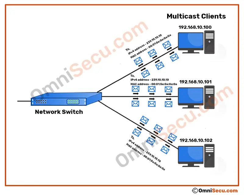
Once the computers 192.168.10.101 and 192.168.10.102 have joined the multicast group 239.10.10.10, they will start accepting Ethernet frames sent with destination MAC address 00:01:5e:0a:0a:0a at layer 2 and pass the decapsulated IPv4 datagram to layer 3 for further processing. The multicast MAC address 00:01:5e:0a:0a:0a is the mapped MAC address for multicast IPv4 address 239.10.10.10.
The computer 192.168.10.100 has not joined the multicast group 239.10.10.10, and it is not interested in Ethernet frames sent to multicast group 239.10.10.10. Hence, computer 192.168.10.100 filters and discards Ethernet frames with destination multicast MAC address 00:01:5e:0a:0a:0a at datalink layer, thus saving its CPU resources.
Have we achieved something here? Yes, the computer 192.168.10.100 is filtering unwanted Ethernet frames at layer 2 and saving its CPU resources. But, have we achieved the main goal of multicast? I guess, No.
Have you noticed something wrong here? In this example, only two computers are interested in receiving multicast traffic from multicast group 239.10.10.10. But the multicast traffic is flooded to all the connected links. The computer 192.168.10.100 is not interested in receiving multicast traffic from multicast group 239.10.10.10, but the link connecting network switch to computer 192.168.10.100 is getting congested with unwanted traffic. We can make multicast better by forwarding multicast traffic belongs to a multicast group only to links connected to computers joined in that group.
To deliver multicast Ethernet frames belongs to a multicast group only to the computers joined in that multicast group, the switch needs to identify its ports (interfaces) through which the computers joined that group are connected (in this example, 230.10.10.10). We have learned earlier in this lesson that devices in a Local Area Network (LAN) use IGMP messages to join and leave a multicast group. But IGMP messages are encapsulated within IPv4 datagram, which is a layer 3 packet. Switches are operating layer 2 of TCP/IP protocol suit. Layer 2 switches deliver Ethernet frames based on source and destination MAC addresses, available at layer 2 header (Ethernet frame header).
Here is the tricky part. If the switches can open and view IGMP join and leave messages, it can learn the multicast group membership related information of the computers connected on its ports. Once the switch is able to identify the group membership related information of computers connected via it’s ports, it can deliver multicast packets belongs to a multicast group only to computers those had joined that multicast group.

Ethernet switches operate at layer 2 (datalink layer) of the TCP/IP protocol suite. Ethernet switches have a feature called as IGMP snooping. As you can see from the previous Wireshark packet capture screenshots in this lesson, IGMP messages are encapsulated in IPv4 datagrams. IGMP snooping allows switches to go up a layer at layer 3 (network layer) and snoop into IGMP header and learn about multicast group membership related information. The switch can then find IGMP join and leave messages sent by computers and maintain a table of interfaces (or ports) joined a specific multicast group. When a switch receives a multicast Ethernet frame for a multicast group, the switch can then forward the frame only out the ports where IGMP joins were received for that multicast group. Thus, IGMP snooping feature of a layer 2 switch helps to prevent unwanted multicast traffic inside the LAN. IGMP snooping enabled switches can save huge bandwidth wastage caused by treating and delivering multicast Ethernet frames similar to broadcast Ethernet frames.